Amd gpio controller driver download
Содержание:
- Pull-up or Pull-down
- Setup UART on the raspi 3 GPIO
- Через что возможно взаимодействовать с GPIO Raspberry
- Writing the Python Software to blink the LED
- Specifications of Model 3B+ :
- What do these conventions omit?
- Interrupts with RPi.GPIO wait_for_edge()
- gpio.pulse.build
- Summary
- I2C, SPI and UART: Which Do You Use?
- Raspberry Pi 4 Specs:
- 10.4. PWM (Pulse-width modulation)
- I2C — Inter-Integrated Circuit
- How to program Raspberry Pi GPIO Pins with Python?
- Introduction to Raspberry Pi 4
- Control Raspberry Pi GPIO via Node-RED Dashboard
- Parts of the Raspberry Pi 3 B+ Model
- Ground (gnd)
- Setting up the circuit
- Explaining the Raspberry Pi GPIO Pinout
Pull-up or Pull-down
In electronic logic circuits, a pull-up resistor or pull-down resistor is a resistor used to ensure a known state for a signal (wiki).
- Pull-up – this option enables the internal pull-up resistor. For GPIO inputs, it means that the pressed state is the LOW signal (connected to the ground).
- Pull-down – For GPIO inputs, it means that the pressed state is the HIGH signal (connected to +3.3V via a 4700 Ohm resistor). You cannot mix internal pull-up or pull-down resistors on the same port.
- External pull-up – similar to the internal pull-up resistor, but you should add it externally on your PCB. It is the main disadvantage. The main advantage, you may mix different pull-up or pull-down types on the same port. A typical resistor value is 4700 Ohm.
- External pull-down – see notes above.
What should you select? It depends on your application and a used external sensor. For GPIO inputs, I prefer “pull-up.” For external sensors, you should look a the sensor’s datasheet for recommended schematics.
Note (CC2530, CC2531): The internal pull-up or pull-down option enabled for one pin automatically selects the same mode for all other pins on the same port P0x, P1x, or P2x. It is the main disadvantage because if you, for example, enable the internal resistor on P0.1, you enable it on P0.2 – P0.7. Therefore it adds limits for mixing different sensors on the same port.
Note (CC2530, CC2531): P10 and P11 pins do not have internal pull-up resistors. Pull-up or pull-down mode does not affect it. I recommend using an external pull-up or external pull-down mode.
Setup UART on the raspi 3 GPIO
For some strange reason the default for Pi3 using the latest 4.4.9 kernel is to DISABLE UART. To enable it you need to change enable_uart=1 in . (There is no longer necessary to add to fix the core frequency to get stable baudrate.)
If you don’t use Bluetooth (or have undemanding uses) it is possible to swap the ports back in the Device Tree. There is a pi3-miniuart-bt and pi3-disable-bt module which are described in /boot/overlays/README here. See end of this article on how to do this.
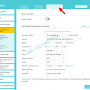
As mentioned, by default the new GPIO UART is not enabled so the first thing to do is to edit the config.txt file to enable the serial UART:
Fig.1. Edit the /boot/config.txt file with nano
To check where your serial ports are pointing you can use the list command with the long “” listing format:
Fig. 2. The /dev directory listing
In the long listing you will find:
serial0 -> ttyS0
serial1 -> ttyAMA0
Thus on a Raspberry Pi 3 and Raspberry Pi Zero W, will point to GPIO J8 pins 8 and 10 and use the . On other Raspberry Pi’s it will point to .
So where possible refer to the serial port via it’s alias of “serial0” and your code should work on both Raspberry Pi 3 and other Raspberry Pi’s.
Disabling the Console (if required)
By default the Raspberry Pi uses the serial port for the “console” login and via a software service called “getty”.
If you are using the serial port for anything other than the console you need to disable it. This will be slightly different depending on whether you are running a Raspberry Pi 3 or not.
For non Raspberry Pi 3 machines, remember it’s /dev/ttyAMA0 that is linked to the getty (console) service.
For Raspberry Pi 3’s the command is referencing /dev/ttyS0:
You also need to remove the console from the cmdline.txt. If you edit this with:
remove the line: and save and reboot for changes to take effect:
To Enable the Serial Console edit the file using:
Exit and save your changes.
Reboot for the changes to take effect.
Test your UART with Python and a terminal emulator
Now, on the Raspberry Pi, type the following code into a text editor, taking care to get the indentation correct:
Save the result as file serialtest.py, and then run it with:
If all is working, you should see the following lines appearing repeatedly, one every 3 seconds, on the terminal emulator:
Say something:
You sent:”
Try typing some characters in the terminal emulator window. You will not see the characters you type appear straight away – instead you will see something like this:
Say something:
You sent:’abcabc’
Swapping the Serial Ports on Raspberry Pi 3
If you don’t want to use the Bluetooth and you want that high performance back on the GPIO, you can do this via a device overlay called “pi3-miniuart-bt” i.e. use the mini-uart () for Bluetooth.
To use add the following line to the /boot/config.txt
Save and reboot for changes to take effect.
You can check that it has worked by:
Swapped Raspberry PI 3 serial port aliases
Another options:
If you want to disable the bluetooth all together, another overlay is available:
END
Через что возможно взаимодействовать с GPIO Raspberry
Работать с GPIO Raspberry Pi можно практически через любой инструмент. К сегодняшнему дню созданы соответствующие библиотеки почти под все распространенные языки программирования. С GPIO Raspberry Pi возможно взаимодействовать даже через PHP и JavaScript (node.js).
Однако человеку, который только начинает знакомиться с «Малиной», рекомендуется пробовать взаимодействовать с данным интерфейсом посредством Python. Это обусловлено, во-первых, что для GPIO в Raspbian уже предустановлена соответствующая библиотека для Пайтона, а, во-вторых, этот ЯП является основным для рассматриваемого одноплатника.
Однако при желании, конечно, возможно пользоваться и любыми другими инструментами. Найти название библиотек и описание их не составляет никакого труда.
Writing the Python Software to blink the LED
With the circuit created we need to write the Python script to blink the LED. Before we start writing the software we first need to install the Raspberry Pi GPIO Python module. This is a library that allows us to access the GPIO port directly from Python.
To install the Python library open a terminal and execute the following
$ sudo apt-get install python-rpi.gpio python3-rpi.gpio
With the library installed now open your favorite Python IDE (I recommend Thonny Python IDE more information about using it here).
Our script needs to do the following:
- Initialize the GPIO ports
- Turn the LED on and off in 1 second intervals
To initialize the GPIO ports on the Raspberry Pi we need to first import the Python library, the initialize the library and setup pin 8 as an output pin.
import RPi.GPIO as GPIO    # Import Raspberry Pi GPIO library
from time import sleep     # Import the sleep function from the time module

GPIO.setwarnings(False)    # Ignore warning for now
GPIO.setmode(GPIO.BOARD)   # Use physical pin numbering
GPIO.setup(8, GPIO.OUT, initial=GPIO.LOW)   # Set pin 8 to be an output pin and set initial value to low (off)
Next we need to turn the LED on and off in 1 second intervals by setting the output pin to either high (on) or low (off). We do this inside a infinite loop so our program keep executing until we manually stop it.
while True: # Run forever
    GPIO.output(8, GPIO.HIGH) # Turn on
    sleep(1)                  # Sleep for 1 second
    GPIO.output(8, GPIO.LOW)  # Turn off
    sleep(1)                  # Sleep for 1 second
Combining the initialization and the blink code should give you the following full Python program:
import RPi.GPIO as GPIO # Import Raspberry Pi GPIO library
from time import sleep # Import the sleep function from the time module

GPIO.setwarnings(False) # Ignore warning for now
GPIO.setmode(GPIO.BOARD) # Use physical pin numbering
GPIO.setup(8, GPIO.OUT, initial=GPIO.LOW) # Set pin 8 to be an output pin and set initial value to low (off)

while True: # Run forever
 GPIO.output(8, GPIO.HIGH) # Turn on
 sleep(1) # Sleep for 1 second
 GPIO.output(8, GPIO.LOW) # Turn off
 sleep(1) # Sleep for 1 second
With our program finished, save it as blinking_led.py and run it either inside your IDE or in the console with:
$ python blinking_led.py
With the program running you should see something like this:
You’ll notice the program keeps on running because of the infinite loop. To stop it click either stop in your IDE or Ctrl+C if you run it inside the console.
Is the LED not blinking? If the LED diode is not blinking try turning it around, maybe you got the polarity wrong (this is perfectly safe).
This guide showed you how to setup a LED to blink using the Raspberry Pi and the Python programming language. For more tips and guides on using electronics with the Raspberry Pi checkout the electronics section and join our newsletter!
Specifications of Model 3B+ :
- Quad-Core 1.4GHz Broadcom BCM2837B0 64bit CPU
- 1GB LPDDR2 SDRAM
- Dual-channel 2.4GHz and 5GHz IEEE 802.11.b/g/n/ac wireless LAN, Bluetooth 4.2, BLE
- Gigabit Ethernet over USB 2.0 with throughput limited to 300 Mbit/s (3 times faster than model B)
- Extended 40-pin GPIO header
- Full-size HDMI
- 4 USB 2.0 ports
- Full-size HDMI CSI (Camera Serial Interface) camera port for connecting a camera
- DSI (Display Serial Interface) display port for connecting a touchscreen display
- 4-pole stereo output and composite video port
- Micro SD port
- 5V/2.5A DC power input
- Power-over-Ethernet (PoE) support (requires separate PoE HAT)
What do these conventions omit?
One of the biggest things these conventions omit is pin multiplexing, since
this is highly chip-specific and nonportable. One platform might not need
explicit multiplexing; another might have just two options for use of any
given pin; another might have eight options per pin; another might be able
to route a given GPIO to any one of several pins. (Yes, those examples all
come from systems that run Linux today.)
Related to multiplexing is configuration and enabling of the pullups or
pulldowns integrated on some platforms. Not all platforms support them,
or support them in the same way; and any given board might use external
pullups (or pulldowns) so that the on-chip ones should not be used.
(When a circuit needs 5 kOhm, on-chip 100 kOhm resistors won’t do.)
Likewise drive strength (2 mA vs 20 mA) and voltage (1.8V vs 3.3V) is a
platform-specific issue, as are models like (not) having a one-to-one
correspondence between configurable pins and GPIOs.
There are other system-specific mechanisms that are not specified here,
like the aforementioned options for input de-glitching and wire-OR output.
Hardware may support reading or writing GPIOs in gangs, but that’s usually
configuration dependent: for GPIOs sharing the same bank. (GPIOs are
commonly grouped in banks of 16 or 32, with a given SOC having several such
banks.) Some systems can trigger IRQs from output GPIOs, or read values
from pins not managed as GPIOs. Code relying on such mechanisms will
necessarily be nonportable.
Interrupts with RPi.GPIO wait_for_edge()
#!/usr/bin/env python3

import RPi.GPIO as GPIO

BUTTON_GPIO = 16

if __name__ == '__main__':
    GPIO.setmode(GPIO.BCM)
    GPIO.setup(BUTTON_GPIO, GPIO.IN, pull_up_down=GPIO.PUD_UP)

    while True:
        GPIO.wait_for_edge(BUTTON_GPIO, GPIO.FALLING)
        print("Button pressed!")
Use the function to wait (block) until a GPIO’s state changes. This function takes 2 (+1 optional) arguments:
- channel: here the GPIO number (BCM mode).
- type of interrupt.
- (optional) timeout.
Here for the type of interrupt we used GPIO.FALLING as the button’s state is HIGH by default, due to the internal pull up resistor.
If you want to wait until the button is released, use GPIO.RISING instead.
And there is a third option: if you want to wait until either the button is pressed or released (both RISING and FALLING), use BOTH. In this case you’ll have to read the button’s state to know if the signal is LOW or HIGH.
For example:
    while True:
        GPIO.wait_for_edge(BUTTON_GPIO, GPIO.BOTH)
        if not GPIO.input(BUTTON_GPIO):
            print("Button pressed!")
        else:
            print("Button released!")
Note: for now we haven’t used any debounce mechanism, so you can sometimes get a weird behavior. A button is a physical system that will bounce when you press or release it, so it may seem like you pressed the button multiple times whereas you only did it once.
gpio.pulse.build
This builds the object from the supplied argument (a table as described below).
Parameter
this is view as an array of instructions. Each instruction is represented by a table as follows:
- All numeric keys are considered to be pin numbers. The values of each are the value to be set onto the respective GPIO line.
For example would set pin 1 to be high.
Note this that is the NodeMCU pin number and not the ESP8266 GPIO number. Multiple pins can be
set at the same time. Note that any valid GPIO pin can be used, including pin 0. - specifies the number of microseconds after setting the pin values to wait until moving to the next state. The actual delay may be longer than this value depending on whether interrupts are enabled at the end time. The maximum value is 64,000,000 — i.e. a bit more than a minute.
- and can be used to specify (along with ) that this time can be varied. If one time interval overruns, then the extra time will be deducted from a time period which has a or specified. The actual time can also be adjusted with the API below.
- and allow simple looping. When a state with and is completed, the next state is at (provided that has not decremented to zero). The count is implemented as an unsigned 32 bit integer — i.e. it has a range up to around 4,000,000,000. The first state is state 1. The is rather like a goto instruction as it specifies the next instruction to be executed.
Example
This will generate a square wave on pins 1 and 2, but they will be exactly out of phase. After 10 seconds, the sequence will end, with pin 2 being high.
Note that you must set the pins into output mode (either gpio.OUTPUT or gpio.OPENDRAIN) before starting the output sequence, otherwise
nothing will appear to happen.
Summary
That wraps up today’s guide on how to use the Raspberry Pi’s GPIO PINs with Python! I hope you’ve gotten a better understanding of the different uses of GPIO and how to use it to interface with sensors and modules for building your own electronics projects.
For more Raspberry Pi resources, please visit the following links:
- How To: 3 Methods to Configure Raspberry Pi WiFi
- 28 Raspberry Pi Linux Commands: A Quick Guide to Use the Command Line for Raspberry Pi
- Build a Raspberry Pi Security Camera using Raspberry Pi Camera!
- Build a Raspberry Pi Line Following Robot!
- Top 35 Raspberry Pi 4 Projects That You Must Try Now
Please follow and like us:
I2C, SPI and UART: Which Do You Use?
We’ll get into the specific differences between I2C, SPI and UART below, but if you’re wondering which one you need to use to connect to given device, the short answer is to check the spec sheet. For example, one tiny LED screen might require SPI and another might use I2C (almost nothing uses UART). If you read the documentation that comes with a product (provided it has some), it will usually tell you which Pi pins to use.
For Raspberry Pi 4 users note that there are now many more I2C, SPI and UART pins available to you. These extra interfaces are activated using device tree overlays and can provide four extra SPI, I2C and UART connections.
Raspberry Pi 4 Specs:
- Broadcom BCM2711 chip consist of Quad-core Cortex-A72 (ARM v8) 64-bit SoC @ 1.5GHz
- 2GB, 4GB, and 8GB of LPDDR4 SDRAM (depending on the version of the board)
- Dual-channel 2.4/5.0 GHz IEEE 802.11ac wireless, Bluetooth 5.0, BLE
- Gigabit Ethernet
- Two USB 3.0 ports and two USB 2.0 ports.
- Raspberry Pi standard 40 pin GPIO header
- Two micro-HDMI ports (support up to 4kp60 resolution)
- 2-lane MIPI DSI display port
- 2-lane MIPI CSI camera port
- 4-pole stereo audio and composite video port
- 265 ( decode), H264 ( decode and encode)
- OpenGL ES 3.0 graphics
- Micro-SD card slot for loading operating system and data storage
- 1V/3A DC via USB-C connector
- Power over Ethernet (PoE) enabled (requires PoE HAT board)
- Operating temperature: 0 – 50oC
10.4. PWM (Pulse-width modulation)
Both libraries support software PWM control on any pin. Depending on the pin
library used, GPIO Zero can also support hardware PWM (using
or ).
A simple example of using PWM is to control the brightness of an LED.
In RPi.GPIO:
import RPi.GPIO as GPIO
from time import sleep

GPIO.setmode(GPIO.BCM)
GPIO.setwarnings(False)

GPIO.setup(2, GPIO.OUT)
pwm = GPIO.PWM(2, 100)
pwm.start()

for dc in range(101):
    pwm.changeDutyCycle(dc)
    sleep(0.01)
In GPIO Zero:
from gpiozero import PWMLED
from time import sleep

led = PWMLED(2)

for b in range(101):
    led.value = b  100.0
    sleep(0.01)
has a method which can be used the same
was as ’s method, but its PWM capabilities allow
for and options to be provided. There is also the
method which provides a neat way to have an LED fade in
and out repeatedly.
I2C — Inter-Integrated Circuit
I2C is a low speed two wire serial protocol to connect devices using the I2C standard. Devices using the I2C standard have a master slave relationship. There can be more than one master, but each slave device requires a unique address, obtained by the manufacturer from NXP, formerly known as Philips Semiconductors. This means that we can talk to multiple devices on a single I2C connection as each device is unique and discoverable by the user and the computer using such as i2cdetect.
As mentioned earlier I2C has two connections: SDA and SCL. They work by sending data to and from the SDA connection, with the speed controlled via the SCL pin. I2C is a quick and easy way to add many different components, such as LCD / OLED screens, temperature sensors and analog to digital converters for use with photoresistors etc to you project. While proving to be a little more tricky to understand than standard GPIO pins, the knowledge gained from learning I2C will serve you well as you will understand how to connect higher precision sensors for use in the field.
The Raspberry Pi has two I2C connections at GPIO 2 and 3 (SDA and SCL) are for I2C0 (master) and physical pins 27 and 28 are I2C pins that enable the Pi to talk to compatible HAT (Hardware Attached on Top) add on boards.
How to program Raspberry Pi GPIO Pins with Python?
What’s unique of running Python on Raspberry Pi instead of the typical PC is that you can run codes specifically to control hardware components through its GPIO pins! In today’s tutorial, we’ll learn how to use GPIO to blink an LED.
You’ll need the following hardware components:
- Raspberry Pi 4 (4GB / 8GB)
- Grove Base Hat for Raspberry Pi
- Grove – Purple LED (3mm)
Hardware Assembly and Configuration
- Plug the Grove Base Hat into Raspberry Pi
- Select any GPIO port on the Base Hat and connect the Purple LED to it
- Connect the Raspberry Pi to PC through USB cable
For step 2, you can connect it to the Grove Port as well, which would result in the pairing to look like this:

Software Configurations with Python
Step 1: Ensure that your development environment is up to date. This should have been done in our earlier steps.
Step 2: Next, download the source file by cloning the grove.py library with the following commands.
Step 3: Execute the following command. Take note to replace port_number with the GPIO port number that your LED is connected to.
If your port number is 12, your command should look like this:
That’s it! You should now be able to see the LED blink!
Introduction to Raspberry Pi 4
The Raspberry Pi 4 Model B is the latest board launched by the Raspberry Pi Foundation in June 2019. This model has the latest high-performance quad-Core 64-bit Broadcom 2711, Cortex A72 processor clocked at 1.5GHz speed.
This processor uses 20% less power and offers 90% greater performance than the previous model. Raspberry Pi 4 GPIO Pinout with functions, schematic, and specs are given in detail below.
Raspberry Pi 4 model comes in three different variants of 2 GB, 4 GB, and 8 GB LPDDR4 SDRAM.
The other new features of the board are dual-display support up to 4k resolutions via a pair of micro-HDMI ports, hardware video decodes at up to 4Kp60, dual-channel 2.4/5.0GHz wireless LAN, true Gigabit Ethernet, two USB 3.0 port, Bluetooth 5.0, and PoE capability (via a separate PoE HAT board).
Control Raspberry Pi GPIO via Node-RED Dashboard
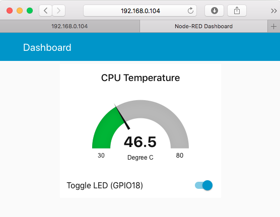
Although the node-RED flow that we created did achieved the result, but it is an editor page, it is not really a web page where user can use. Won’t it be better to have a graphical UI like the one shown below? sure, let’s do it.
 Simple GPIO Dashboard
What you seen requires Node-RED Dashboard, an add-on that you could installed via npm. To install it, navigate to the user node-red directory which is at or if you are running Raspberry Pi as user.
cd ~/.node-red
npm install node-red-dashboard
Node-RED dashboard can be access via , however the path is disabled by default, we need to change the setting at . Use nano editor to make the change:
nano settings.js
Press or simple scrolling down to search for line with and uncomment out the line by deleting the in front of the line. Pressed to save the file.
If you had configured to run node-RED as a daemon service (i.e. auto-run at boot up), you will need to restart the node-red for the change to take on effect:
sudo systemctl restart node-red
But if you are running node-RED manually as we described in this article, you can ignore this restart command. Now let’s create our dashboard.
You will noticed that there is an newly installed “Dashboard” category on the node palette, these are the UI widgets can be displayed on the Dashboard. First, let’s create a new flow by clicking on the + icon on the right side of the flow tab.
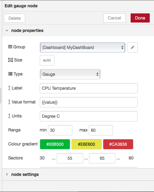
- Drag a “gauge” dashboard node to the new flow that we just created, this will be used for displaying GPU Temperature;
- Double click on the gauge and click on the Edit (the little Pen icon) to “Add new ui_group”, and give it a name (e.g. “MyDashboard”), also name the dashboard screen as “Dashboard”, this will eventually displayed on the screen as page title;
- Set the temperature range, and other properties. In this example, we set minimum to 30 and maximum to 80, and set the Units as Degree C.
- Drag an “inject” node and an “exec” node into the flow, configure them and wire them together just like what we did previously;
- Drag a “switch” dashboard node to the flow and configure the UI_group to be same as the UI_group used by the gauge. The “switch” node will replaced the two “inject” nodes that we used to control the GPIO because the “switch” node can toggle between two statuses.
- Drag a “rpi gpio” output node and wire together with our new “switch” node.
 Gauge configuration
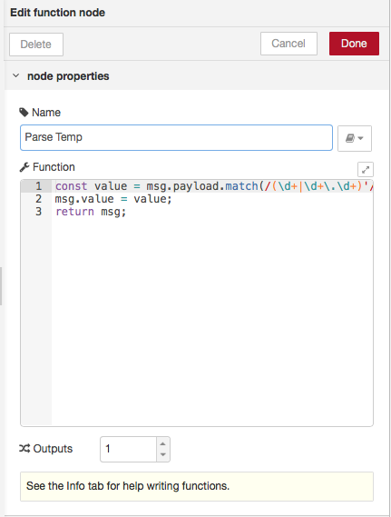
As you may noticed from the previous example, the “exec” node return a string like as . However the “gauge” is expecting a to be used as the temperature display for the gauge, not a string. So we will need to do some parsing between the “exec” node and the “gauge” display. We can do that with a “function” node, the “function” allows us to write a JavaScript function to parse the string and return the temperature data as for the gauge to consume.
 Function node for parsing temperature
The parse temp function in Javascript
const value = msg.payload.match(/(\d+|\d+\.\d+)'/);
msg.value = value;
return msg;
Now we can insert the “function” node between the “wire” node and the “gauge” node and wire them up.
Point your browser to , you should be able to see the Gauge and Toggle switch grouped within the same UI group. Click on the switch will toggle the LED on and off.
Parts of the Raspberry Pi 3 B+ Model
 Parts of Raspberry Pi 3 B+
Processor: The BCM2837B0 processor is the main component of this tiny board that helps in carrying out a large set of instructions based on mathematical and logical formulas. BCM2837B0 is a 1.4GHz 64bit ARM quad-core Cortex A53 processor.
RAM: RAM used in R-Pi 3 B+ is 1GB LPDDR2 SDRAM (similar to the previous version)
GPU: It stands for graphics processing unit and is used for performing out the image calculation. The GPU uses OpenGL ES version 2.0, hardware-accelerated OpenVG API, and 1080p30 H.264 high-profile decode. It can provide up to 1Gpixel/s, 1.5Gtexel/s, or 24 GFLOPs of a general-purpose computer.
USB Ports: Similar to model B, model B+ also consists of 4 USB ports. Thus removing the hassle of connecting the USB hub in order to increase the ports.
Micro USB Power Source Connector: This connector is used for delivering 5V power to the board. It consumes approx. 170 to 200mA more power than model B. The power connector is also repositioned in the new B+ model and placed next to the HDMI socket.
HDMI and Composite Connection: Both the audio output socket and the video composite socket reside in a single 4-pole 3.5mm socket which is placed near the HDMI port, and now all the power and audio-video composite socket are placed on the one side of the board which gives it a clean and nice look.
USB Hard Drive: The board is capable of using an external USB hard drive.
PoE: B+ model comes with a facility of Power over Ethernet (PoE); a new feature added in this device which allows us to power the board using the ethernet cables.
Other Changes: The B+ version also comes with other improvements like the SD memory slot is replaced by a micro SD memory card slot (works similar to the previous version). The status LEDs on the board now only contain red and green colors and are relocated to the opposite end of the board.
Ground (gnd)
Ground is commonly referred to as GND, gnd or — but they all mean the same thing. GND is where all voltages can be measured from and it also completes an electrical circuit. It is our zero point and by connecting a component, such as an LED to a power source and ground the component becomes part of the circuit and current will flow through the LED and produce light.
When building circuits it is always wise to make your ground connections first before applying any power as it will prevent any issues with sensitive components. The Raspberry Pi has eight ground connections along the GPIO and each of these ground pins connects to one single ground connection. So the choice of which ground pin to use is determined by personal preference, or convenience when connecting components.
Setting up the circuit
The first step in this project is to design a simple LED circuit. Then we will make the LED circuit controllable from the Raspberry Pi by connecting the circuit to the general purpose input/output (GPIO) pins on the Raspberry Pi.
A simple LED circuit consists of a LED and resistor. The resistor is used to limit the current that is being drawn and is called a current limiting resistor. Without the resistor the LED would run at too high of a voltage, resulting in too much current being drawn which in turn would instantly burn the LED, and likely also the GPIO port on the Raspberry Pi.
To calculate the resistor value we need to examine the specifications of the LED. Specifically we need to find the forward voltage (VF) and the forward current (IF). A regular red LED has a forward voltage (VF) of 1.7V and forward current of 20mA (IF). Additionally we need to know the output voltage of the Raspberry Pi which is 3.3V.
We can then calculate the resistor size needed to limit the current to the LED’s maximum forward current (IF) using ohm’s law like this:
\
Unfortunately 80 ohm is not a standard size of a resistor. To solve this we can either combine multiple resistors, or round up to a standard size. In this case we would round up to 100 ohm.
Important information Since ohm’s law tells us that I (current) = V (voltage) / R (ohm) rounding up the resistor value will lower the actual current being drawn a little. This is good because we don’t want to run our system at the maximum current rating. Rounding down instead of up would be dangerous, since it will actually increase the current being drawn. Increased current would result in running our system over the maximum rating and potentially destroying or damaging our components.
With the value calculated for the current limiting resistor we can now hook the LED and resistor up to GPIO pin 8 on the Raspberry Pi. The resistor and LED needs to be in series like the diagram below. To find the right resistor use the resistor color code – for a 100 ohm resistor it needs to be brown-black-brown. You can use your multimeter to double check the resistor value.
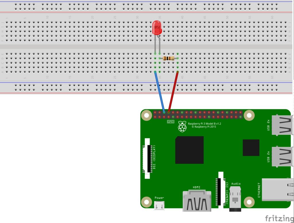
When hooking up the circuit note the polarity of the LED. You will notice that the LED has a long and short lead. The long lead is the positive side also called the anode, the short lead is the negative side called the cathode. The long should be connected to the resistor and the short lead should be connected to ground via the blue jumper wire and pin 6 on the Raspberry Pi as shown on the diagram.
To find the pin number refer to this diagram showing the physical pin numbers on the Raspberry Pi. 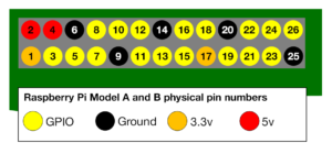
Explaining the Raspberry Pi GPIO Pinout
If you’re using the Raspberry Pi B+, 2 , 3, Zero or the latest Raspberry Pi 4 Model B, you’ll find a total of 40 GPIO pins on your RPi’s GPIO header. Older iterations of the RPI, such as the Raspberry Pi Model B, will only contain a total of 26pins.
Source: Raspberry Pi Foundation
Each of the pins on the 40 Pin header have a designated purpose. The different types are described in the table below.
| GPIO Pin Type | Pin Functionality and Explanation |
|---|---|
| GPIO | GPIO pins are standard general-purpose pins that can be used for turning external devices, such as an LED, on or off. |
| Power | 5V and 3V3 pins are used to supply 5V and 3.3V power to external components. |
| I2C | I2C pins are used for connecting and hardware communication purposes with I2C compatible external modules. |
| SPI | SPI (Serial Peripheral Interface Bus) pins are also used for hardware communication, but with a different protocol. |
| UART | UART (Universal Asynchronous Receiver / Transmitter) pins are used for serial communication. |
| DNC | Use of DNC (Do Not Connect) pins should be avoided. |
| GND | GND (Ground) pins refer to pins that provide electrical grounding in your circuits. |
For more information on the differences between and uses of PWM, I2C, SPI, UART protocols, please refer to the following resources:
- What is Pulse Width Modulation (PWM)? Applications and Accessories
- UART vs I2C vs SPI – Communication Protocols and Uses
- I2C Communication – All about I²C with Diagrams