Rpi.gpio 0.7.0
Содержание:
- Установка необходимых пакетов для работы с Bluetooth в Raspberry Pi
- 4.3. Environment variables
- Python (RPi.GPIO) Example
- Introduction
- Viewing temperature on this web page
- Ground (gnd)
- Шаг 4: калибровка сервоприводов
- Shopping List
- How to program Raspberry Pi GPIO Pins with Python?
- Parts of the Raspberry Pi 3 B+ Model
- Python – это основной язык Raspberry Pi
- Gpiozero
- How to Configure Raspberry Pi GPIO, I2C, and SPI Pins
- A Bit About Python
- Что такое GPIO и для чего он нужен?
- Распиновка GPIO Raspberry Pi 3 model b
- Explaining the Raspberry Pi GPIO Pinout
- C (WiringPi) Setup
- Binary Sensor
- Итог: что понадобится для работы с GPIO
Установка необходимых пакетов для работы с Bluetooth в Raspberry Pi
Первым делом нам необходимо установить последние обновления для операционной системы Raspberry Pi OS:
Shell
sudo apt-get update
sudo apt-get upgrade
|
1 |
sudo apt-getupdate sudo apt-getupgrade |
Затем нам необходимо установить последние обновления для работы с Bluetooth:
Shell
sudo apt-get install bluetooth blueman bluez
| 1 | sudo apt-getinstall bluetooth blueman bluez |
После этого необходимо перезагрузить плату Raspberry Pi:
Shell
sudo reboot
| 1 | sudo reboot |
BlueZ – это проект с открытым исходным кодом и официальный стек протоколов Bluetooth для операционной системы Linux. Он поддерживает все ядро протоколов Bluetooth и в настоящее время является официальной частью Linux Kernel (ядра Linux).
Blueman обеспечивает интерфейс рабочего стола для управления Bluetooth устройствами.
Также нам потребуется библиотека Python для работы с протоколом Bluetooth чтобы мы могли в программе передавать и принимать данные через RFCOMM:
Shell
sudo apt-get install python-bluetooth
| 1 | sudo apt-getinstall python-bluetooth |
Также необходимо установить библиотеку обеспечения работы с контактами ввода/вывода (GPIO) в Raspberry Pi:
Shell
sudo apt-get install python-rpi.gpio
| 1 | sudo apt-getinstall python-rpi.gpio |
На этом установка всех необходимых пакетов для работы с Bluetooth в Raspberry Pi будет закончена.
4.3. Environment variables
The simplest way to use devices with remote pins is to set the
environment variable to the IP address of the desired
Raspberry Pi. You must run your Python script or launch your development
environment with the environment variable set using the command line. For
example, one of the following:
$ PIGPIO_ADDR=192.168.1.3 python3 hello.py
$ PIGPIO_ADDR=192.168.1.3 python3
$ PIGPIO_ADDR=192.168.1.3 ipython3
$ PIGPIO_ADDR=192.168.1.3 idle3 &
If you are running this from a PC (not a Raspberry Pi) with gpiozero and the
pigpio Python library installed, this will work with no further
configuration. However, if you are running this from a Raspberry Pi, you will
also need to ensure the default pin factory is set to
. If RPi.GPIO is installed,
this will be selected as the default pin factory, so either uninstall it, or
use the environment variable to override it:
$ GPIOZERO_PIN_FACTORY=pigpio PIGPIO_ADDR=192.168.1.3 python3 hello.py
This usage will set the pin factory to
with a default host of
. The pin factory can be changed inline in the code, as seen in
the following sections.
With this usage, you can write gpiozero code like you would on a Raspberry Pi,
with no modifications needed. For example:
from gpiozero import LED
from time import sleep

red = LED(17)

while True
    red.on()
    sleep(1)
    red.off()
    sleep(1)
When run with:
$ PIGPIO_ADDR=192.168.1.3 python3 led.py
will flash the LED connected to pin 17 of the Raspberry Pi with the IP address
. And:
$ PIGPIO_ADDR=192.168.1.4 python3 led.py
will flash the LED connected to pin 17 of the Raspberry Pi with the IP address
, without any code changes, as long as the Raspberry Pi has the
pigpio daemon running.
Python (RPi.GPIO) Example
Follow along as we use the basic RPi.GPIO functions from the last page to create a simple example GPIO script.
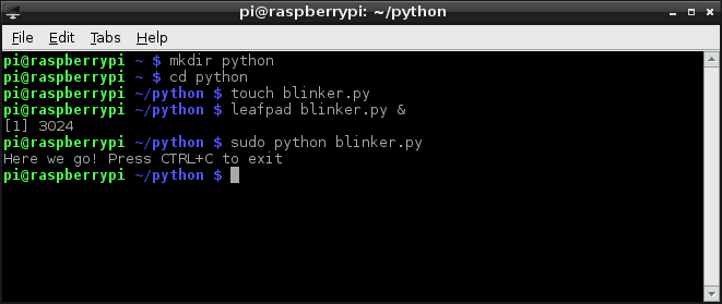
1. Create a File
To begin, we need to create a Python file. You can do this through the GUI-based file explorer. Or, if you want a terminal-based solution, open up LXTerminal, and navigate to a folder you’d like the file to live (or create one). And create a new folder with these commands:
Then move to the folder with the following command.
Create a file — we’ll call ours «blinker» — and terminate it with a .py extension.
Then open it up in your favorite text editor. Nano works, as does Pi’s default GUI text editor, Mousepad.
Note: Previously, Leafpad was the default GUI text editor for Raspberry Pi Images. It is now replaced by Mousepad. You can find Mousepad under the Raspberry Pi Start Menu under Accessories > Text Editor. You can still install leafpad manually with the command. Once installed, you can specify the text editor to open up the file.
That’ll open up a blank text file (the «&» will open it in the background, leaving the terminal in place for future use). Time for some code!
2. Codify
Here’s an example sketch that incorporates everything we learned on the last page. It does a little input and output, and even handles some PWM. This assumes you’ve set up the circuit as arranged on the Hardware Setup page.
After you’ve typed all of that in (don’t forget your whitespace!) save.
Running the Script
The RPi.GPIO module requires administrator privileges, so you’ll need to tag a on to the front of your Python script call. To run your «blinker.py» script, type:
With the code running, press the button to turn on the digital LED. The PWM-ing LED will invert its brightness when you press the button as well.
Introduction
Relative to its size the Raspberry Pi is a powerhorse of a computer — it can drive HDMI displays, process mouse, keyboard, and camera inputs, connect to the Internet, and run full-featured Linux distributions. But it’s more than just a small computer, it’s a hardware prototyping tool! The Pi has bi-directional I/O pins, which you can use to drive LEDs, spin motors, or read button presses.
This tutorial was written originally for the Raspberry Pi Model B but applies for any Raspberry Pi Models with the standard 2×20 header.
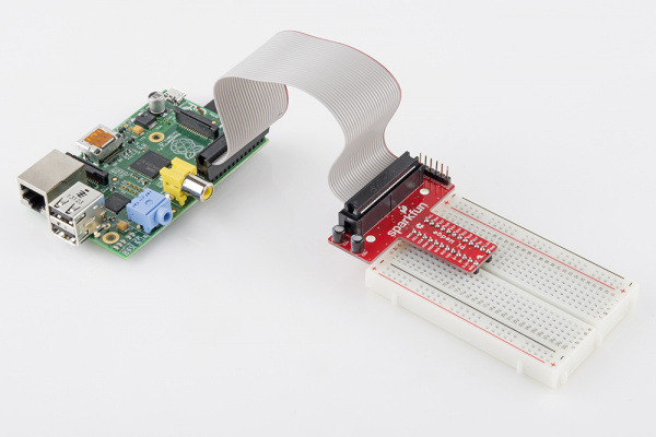
Example Pi Wedge on a Model B
Driving the Raspberry Pi’s I/O lines requires a bit of programming. Programming in what language? Take your pick! A quick glance at the shows that there are dozens of programming-language-choices. We’ve pared that list down, and ended up with two really solid, easy tools for driving I/O: Python and C (using the WiringPi library).
If you’ve never driven an LED or read in a button press using the Raspberry Pi, this tutorial should help to get you started. Whether you’re a fan of the easily-readable, interpretive scripting language Python or more of a die-hard C programmer, you’ll find a programming option that suits our needs.
Covered In This Tutorial
In this tutorial we’ll show two different approaches to reading and driving the Raspberry Pi’s GPIO pins: python and C. Here’s a quick overview of what’s covered:
- GPIO Pinout — An overview of the Pi’s GPIO header.
-
Python API and Examples
- RPi.GPIO API — An overview of the Python functions you can use to drive GPIO.
- RPi.GPIO Example — An example Python script that shows off both input and output functionality.
-
C (and WiringPi) API and Examples
- WiringPi Setup and Test — How to install WiringPi and then take it for a test drive on the command line.
- WiringPi API — An overview of the basic functions provided by the WiringPi library.
- WiringPi Example — A simple example program that shows off WiringPi’s input and output capabilities.
- Using an IDE — How to download and install Geany. Our favorite IDE for programming on the Raspberry Pi.
Each programming language has it’s share of pros and cons. Python is easy (especially if your a programming novice) and doesn’t require any compilation. C is faster and may be easier for those familiar with the old standby.
What You’ll Need
Here’s a wishlist-full of everything we used for this tutorial.
Some further notes on that bill of materials:
- Your Raspberry Pi should have an SD card with Raspbian installed on it. Check out our How to Install Raspbian tutorial for help with that.
- We’re also assuming you have the necessary mouse, keyboard and display hooked up to your Pi.
- Your Pi will need an Internet connection to download WiringPi. You can use either Ethernet or WiFi (check out our Raspberry Pi WiFi tutorial for help with that.
- The Pi Wedge isn’t quite required, but it does make life a lot easier. If you want to skip the breakout, you can instead use Male-to-Female jumpers to connect from Pi to breadboard.
- Of course, feel free to swap in your preferred button and LEDs.
Suggested Reading
This tutorial will assume you have Raspbian installed on your Raspberry Pi. Raspbian is the most popular, well-supported Linux distribution available for the Pi. If you don’t have Raspbian set up, check out our Setting Up Raspbian tutorial before continuing down this rabbit hole.
Other, more general purpose tutorials you might be interested in reading include:
- Pulse-Width Modulation — You can use PWM to dim LEDs or send signals to servo motors. The RPi has a single PWM-capable pin.
- Light-Emitting Diodes (LEDs) — To test the output capabilities of the Pi, we’ll be driving a lot of LEDs.
- Switch Basics — And to test inputs to the Pi, we’ll be using buttons and switches.
- Pull-Up Resistors — The Pi has internal pull-up (and pull-down) resistors. These are very handy when you’re interfacing buttons with the little computer.
Viewing temperature on this web page
1. Create a file called temperature.php:
2. Add the following code to it, replace 10-000802292522 with your device ID:
<?php//File to read$file = '/sys/devices/w1_bus_master1/10-000802292522/w1_slave';//Read the file line by line$lines = file($file);//Get the temp from second line$temp = explode('=', $lines1);//Setup some nice formatting (i.e., 21,3)$temp = number_format($temp1 1000, 1, ',', '');//And echo that tempecho $temp . " °C";?>
3. Go to the HTML file that you just created, and create a new <div> with the id “screen”: <div id=“screen”></div>.
4. Add the following code after the <body> tag or at the end of the document:
<script>
$(document).ready(function(){
setInterval(function(){
$("#screen").load('temperature.php')}, 1000);});</script>
In this, #screen is the id of <div> in which you want to display the temperature. It loads the temperature.php file every 1000 milliseconds.
I have used bootstrap to make a beautiful panel for displaying temperature. You can add multiple icons and glyphicons as well to make it more attractive.
Ground (gnd)
Ground is commonly referred to as GND, gnd or — but they all mean the same thing. GND is where all voltages can be measured from and it also completes an electrical circuit. It is our zero point and by connecting a component, such as an LED to a power source and ground the component becomes part of the circuit and current will flow through the LED and produce light.
When building circuits it is always wise to make your ground connections first before applying any power as it will prevent any issues with sensitive components. The Raspberry Pi has eight ground connections along the GPIO and each of these ground pins connects to one single ground connection. So the choice of which ground pin to use is determined by personal preference, or convenience when connecting components.
Шаг 4: калибровка сервоприводов
У SG90 от различных производителей (могут выпускаться со своей наклейкой, например, «FeeTech FS90» или как в оригинальной «TowerPro SG90») параметры сервопривода могут немного отличаться. Если питающее напряжение обычно до 4.8-5в, частота управляющих импульсов 50Гц (т.е. период следования сигнала 20мс), а угол, на который проворачивается сервопривод примерно 180градусов, то длительность управляющего импульса очень часто отличается.
К примеру длительность управляющего импульса может быть от 1мс до 2мс или от 0.75мс до 1.85мс или от 0.5мс до 2.4мс и т.д. Для сервоприводов от одного производителя, длительность управляющего импульса тоже может немного отличаться. Калибровка — это определение, какие длительности импульсов соответствуют минимальной и максимальной длительность управляющего импульса и каким углам проворачивания вала сервопривода они соответствуют.

Под нейтральным положением может подразумеваться то положение, в которое проворачивается вал при средней длительности импульса (в данном случае это 1.5мс). Обозначать в градусах могут как на картинке выше, т.е. нейтральное 90 градусов и крайние положения как 0 и 180. Или под нейтральным подразумевать 0 градусов, а крайние обозначать как -90 и +90. С обозначениями углов это условность, могут быть и другие варианты. В данном случае будет использоваться первый вариант.
Для программирования позиции сервопривода с использованием Python очень важно знать соответствующий коэффициент заполнения (англ. duty cycle) для вышеуказанных позиций (задаётся в процентах)
К примеру длительность импульса 2мс, при периоде следования сигнала 20мс это коэффициент заполнения 10%. Давайте сделаем вычисления для всех углов:
- исходное положение ==> (0 градусов) длительность импульса 1мс ==> коэффициент заполнения = 1мс/20мс*100% = 5%
- нейтральное положение ==> (90 градусов) длительность импульса 1,5мс ==> коэффициент заполнения = 1,5мс/20мс*100% = 7,5%
- конечная позиция ==> (180 градусов) длительность импульса 2мс ==> коэффициент заполнения = 2мс/20мс*100% = 10%
Таким образом коэффициент заполнения варьируется от 5% до 10%.
Давайте откалибруем сервоприводы. Для этого откроем терминал на Raspberry и запустим редактор Python 3 с правами от суперпользователя (нужно для работы с GPIO):
sudo python3
Python Shell:
>>>
Импортируем модуль RPI.GPIO и называем его GPIO:
import RPi.GPIO as GPIO
Определите, какие схемы нумерации выводов хотите использовать (BCM или BOARD). Я провел этот тест с BOARD, поэтому используемые контакты были физическими (GPIO 17 это контакт 11 и GPIO 27 это контакт 13). Мне было легко их идентифицировать и не ошибиться во время теста (в финальной программе я буду использовать BCM). Выбираем:
GPIO.setmode(GPIO.BOARD)
Определяем вывод сервопривода, который будет использоваться:
tiltPin = 11
Если хотите использовать схему BCM, последние 2 команды должны быть заменены на:
GPIO.setmode(GPIO.BCM)
tiltPin = 17
Теперь указываем, что этот вывод будет работать как выход:
GPIO.setup(tiltPin, GPIO.OUT)
Настраиваем частоту, для SG90 нужно 50 Гц:
tilt = GPIO.PWM(tiltPin, 50)
Включаем генерацию сигнала ШИМ на выводе и задаём начальный коэффициент заполнения равный нулю:
tilt = start(0)
Теперь мы можем устанавливать различные значения коэффициента заполнения и наблюдать за движением сервопривода. Давайте начнем с 5% и посмотрим, что происходит:
tilt.ChangeDutyCycle(5)
Сервопривод перешел в «нулевое положение». Сервопривод продолжал вращаться, при задании заполнения вплоть до 3%. При задании заполнения 2% сервопривод оставался в том же положении. После чего начав задавать значения больше 2%, движение сервопривода в моём случае начало происходить при установке коэффициента заполнения более 3%. Итак, 3% — это минимальное заполнение (позиция «0 градусов») для этого сервопривода.
То же самое произошло и с максимальным коэффициентом заполнения. Для начала установлено 10%:
tilt.ChangeDutyCycle(10)
Затем задавались большие значения, сервопривод продолжал проворачиваться при установке коэффициента заполнения вплоть до 13%. Таким образом максимальный коэффициент заполнения для данного сервопривода это 13%, угол, на который проворачивается вал сервопривода составил примерно 180 градусов (но это в данном случае, в зависимости от сервопривода физический угол может оказаться и больше и меньше). Итак, в результате калибровки получены следующие данные:
После окончания калибровки останавливаем ШИМ и очищаем GPIO:
tilt=stop()
GPIO.cleanup()
Для второго сервопривода процедура калибровки аналогична.
Shopping List
To try this out, you will need the following (links here mostly go to Adafruit, UK customers may want to consider Pimoroni as a UK based alternative, Amazon has most if not all of this stuff too):
- A Raspberry Pi (I’ll use the Pi 3 Model B here, but any model with GPIO pins will work — if you want to use the Pi Zero you’ll need to solder some headers onto it). I’m going to assume you have a Pi 2 or 3 with 40 pins
- A power supply for your Pi (Raspberry Pi 4 requires a different USB C power supply)
- Some sort of case is probably a good idea to protect the Pi (but you’ll need to leave the lid off to expose the GPIO pins to connect your lights to)
- A Micro SD card to install your operating system on (or get one with the OS pre-installed). If you want to install the operating system yourself, you’ll need a Mac, PC, Linux machine with an SD card reader
- A set of traffic lights from Low Voltage Labs (the two pack is good value)
- Any USB keyboard to type on the Pi, you might want a mouse too
- Any HDMI display to show output from the Pi
How to program Raspberry Pi GPIO Pins with Python?
What’s unique of running Python on Raspberry Pi instead of the typical PC is that you can run codes specifically to control hardware components through its GPIO pins! In today’s tutorial, we’ll learn how to use GPIO to blink an LED.
You’ll need the following hardware components:
- Raspberry Pi 4 (4GB / 8GB)
- Grove Base Hat for Raspberry Pi
- Grove – Purple LED (3mm)
Hardware Assembly and Configuration
- Plug the Grove Base Hat into Raspberry Pi
- Select any GPIO port on the Base Hat and connect the Purple LED to it
- Connect the Raspberry Pi to PC through USB cable
For step 2, you can connect it to the Grove Port as well, which would result in the pairing to look like this:

Software Configurations with Python
Step 1: Ensure that your development environment is up to date. This should have been done in our earlier steps.
Step 2: Next, download the source file by cloning the grove.py library with the following commands.
Step 3: Execute the following command. Take note to replace port_number with the GPIO port number that your LED is connected to.
If your port number is 12, your command should look like this:
That’s it! You should now be able to see the LED blink!
Parts of the Raspberry Pi 3 B+ Model
 Parts of Raspberry Pi 3 B+
Processor: The BCM2837B0 processor is the main component of this tiny board that helps in carrying out a large set of instructions based on mathematical and logical formulas. BCM2837B0 is a 1.4GHz 64bit ARM quad-core Cortex A53 processor.
RAM: RAM used in R-Pi 3 B+ is 1GB LPDDR2 SDRAM (similar to the previous version)
GPU: It stands for graphics processing unit and is used for performing out the image calculation. The GPU uses OpenGL ES version 2.0, hardware-accelerated OpenVG API, and 1080p30 H.264 high-profile decode. It can provide up to 1Gpixel/s, 1.5Gtexel/s, or 24 GFLOPs of a general-purpose computer.
USB Ports: Similar to model B, model B+ also consists of 4 USB ports. Thus removing the hassle of connecting the USB hub in order to increase the ports.
Micro USB Power Source Connector: This connector is used for delivering 5V power to the board. It consumes approx. 170 to 200mA more power than model B. The power connector is also repositioned in the new B+ model and placed next to the HDMI socket.
HDMI and Composite Connection: Both the audio output socket and the video composite socket reside in a single 4-pole 3.5mm socket which is placed near the HDMI port, and now all the power and audio-video composite socket are placed on the one side of the board which gives it a clean and nice look.
USB Hard Drive: The board is capable of using an external USB hard drive.
PoE: B+ model comes with a facility of Power over Ethernet (PoE); a new feature added in this device which allows us to power the board using the ethernet cables.
Other Changes: The B+ version also comes with other improvements like the SD memory slot is replaced by a micro SD memory card slot (works similar to the previous version). The status LEDs on the board now only contain red and green colors and are relocated to the opposite end of the board.
Python – это основной язык Raspberry Pi
Почти все владельцы Raspberry Pi понимают, что означает первое слово в названии одноплатника – «малина». Однако второе многие интерпретируют неверно.
Некоторые считают, что оно означает «Пи» (3,14…), другие думают, что это первые две буквы слова Pie (пирог, и в этом есть смысл – «малиновый пирог»). Однако на деле все иначе.
Pi – это сокращение от Python, только с заменой y на i. Так часто делают в программировании. Взять, например, хотя бы KDE, где во многих программах вместо С написано K (в угоду стилю): Konsole (правильно – Console), Konqueror (Conqueror) и т. д.
То есть, как не трудно догадаться, в Raspberry основным языком является «Пайтон». Поэтому владельцу «Малины», который пока не знает никакого ЯП, рекомендуется изучать именно этот. Причин, почему Raspberry Pi 3 программирование на Python наиболее лучшее решение, существует множество.
Вот лишь некоторые из них:
- работа из коробки в Raspbian;
- наличие обширной, хорошо документированной официальной библиотеки, которая уже включена в пакет;
- простота языка и т. д.
Примеры кода на Python для Raspberry
Здесь по понятным причинам не будем рассказывать о языке и особенностях программирования на нем – это можно и нужно делать на официальных ресурсах (или, если не позволяет плохое знание английского – на специализированных).
Вместо этого будет рассмотрено, насколько легко можно программировать «Малину». Для примера возьмем Raspberry Pi 3 GPIO программирование. Сделаем предположение, что в наличии имеется все необходимое: провода, светодиод, резистор и прочее, а также присутствует понимание распиновки – нумерации пинов. Также предположим, что светодиод подключен к 11 порту.
Написанный ниже код включает лампочку на 5 секунд, а затем выключает ее:
# вначале подключим необходимую библиотеку
import RPi.GPIO as GPIO
# также понадобится библиотека, которая отвечает за ожидание (она нужна, чтобы установить интервал включения и выключения лампочки)
import time
# чтобы запустить GPIO, понадобится выполнить следующую функцию
GPIO.setmode(GPIO.BOARD)
# теперь Python знает о GPIO, и ему можно указать на то, с каким портом нужно будет работать и что он должен делать (в данном случае – 11-м и он будет работать на выход)
GPIO.setup(11, GPIO.OUT)
# далее включим лампочку на 5 секунд (11 – номер порта, а 1 – значит true)
GPIO.output(11, 1)
time.sleep(5)
# теперь выключим (0 – значит false)
GPIO.output(11, 0)
Указанный код можно скопировать, вставить в документ и сохранить его с расширением .py, расположив, например, в домашней директории. Затем его нужно запустить командой: python ~./имя_файла.py.
Если все работает, то оборудование исправно.
Следует отметить, что, если вы плохо понимаете вышеуказанный код, обратитесь к документации и изучите основы программирования на Python, а также библиотеку GPIO. А если у вас есть хотя бы базовое понимание любого ЯП, то осознаете, что приведенный пример предельно прост.
Gpiozero
A newer GPIO library for the Raspberry Pi is gpiozero . Created by Ben Nuttall of the Raspberry Pi Foundation and other contributors it is released under an MIT-type free software license.
While newer than Rpi.GPIO, it is now generally recommended to use it for new programming. It can have a longer learning because it offers more features that Rpi.GPIO, but the resulting code is usually very clean and readable.
We’ll look at a few simple examples of how to use it.
Documentation is excellent, and presents many «recipes» showing how to control various devices from LEDs to switches to motion sensors, servers, and robots.
Gpiozero should be installed by default on Raspian Linux unless you installed the «lite» version. If needed, it can be installed using the command:
sudo apt install python3-gpiozero
Gpiozero provides may different modules or «interfaces». You typically import the ones you use by name so you can refer to them with a short name. For example:
from gpiozero import LED
to allow using the gpiozero.LED module and refer to it as «LED». You can import multiple modules with one import statement, e.g.
from gpiozero import LED, Button
The GPiozero library uses Broadcom (BCM) pin numbering rather than physical pin numbers. That should not normally be a problem. It does define names based on other naming conventions like physical pins that can be used and will be converted to the BCM names. The following examples will all work for an LED that is on GPIO 17 on physical pin 11:
led = LED(17)
led = LED(«GPIO17»)
led = LED(«BCM17»)
led = LED(«BOARD11»)
led = LED(«WPI0»)
led = LED(«J8:11»)
A handy command line tool called «pinout» is part of the library and will graphically show you the GPIO pins for the board it is running on (or any board revision that you specify):
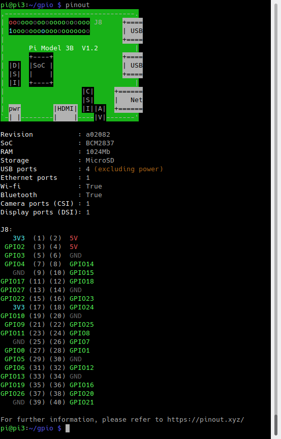
The library is oriented around device and sensor types rather than inputs and outputs. For driving an output connected to an LED, for example, you use the LED module. You create an instance by passing the GPIO name. You can then call various methods like on() and off(). Here is a simple example that flashes and LED:
#!/usr/bin/python3
from gpiozero import LED
from time import sleep
led = LED(24)
while True:
led.on()
sleep(1)
led.off()
sleep(1)
The above loop could also be done by simply calling:
red.blink()
Which blinks an LED, defaulting to a rate of one second on and one second off.
Inputs pins are often connected to buttons, and in this case you can use the Gpiozero Button module, as in this example:
#!/usr/bin/python3
from gpiozero import Button
from time import sleep
button = Button(6)
while True:
if button.is_pressed:
print(«Button is pressed»)
else:
print(«Button is not pressed»)
sleep(1)
We can easily connect a switch so that when a pressed or released event occurs, we drive an LED high or low. This is event drived, so once set up, this works without any polling or further processing:
#!/usr/bin/python3
from gpiozero import LED, Button
from signal import pause
led = LED(24)
button = Button(6)
button.when_pressed = led.on
button.when_released = led.off
pause()
The call to pause() ensures that our Python program does not exit immediately, but rather keeps running until the user interrupts it with Control-C or similar.
Gpiozero has support for many devices — you can explore the documentation and try writing programs of your own. You can also extend it for new types of devices and sensors.
How to Configure Raspberry Pi GPIO, I2C, and SPI Pins
Now that we know more about the Raspberry Pi’s GPIO, it’s time to get started with physical computing! Similar to other electrical components, we first have to configure the GPIO pins before using them. The configuration guide below will be run on Raspberry Pi OS.
Configuring GPIO
If you’re running the latest version of Raspberry Pi OS, you can skip these steps and get straight into programming with GPIO!
Otherwise, you’ll have to run the following commands in the serial terminal to update your RPI:
If for any reason you don’t have the GPIO package installed, you can run the following command for installation:
Configuring Raspberry Pi I2C / SPI Pins
To enable I2C or SPI for hardware communication, we’ll use the Raspi-Config tool by entering the following command:
In the menu that shows up, navigate to Advanced Options > I2C and select yes. For SPI, navigate to Advanced Options > SPI instead. Once complete, reboot your RPi and your I2C pins will be enabled. To ensure that I2C communication is working properly with your RPi, connect your modules and enter the command below:
For SPI, run the following command instead:
In each case, the command line should then return a list indicating the modules that you’re running through the I2C / SPI pins.
A Bit About Python
Python is an interpreted, high-level, general-purpose programming language that has been around since 1991. It is currently one of the most popular and fastest growing programming languages. The «Pi» in Raspberry Pi standards for «Python Interpreter,» reflecting the fact that this is the recommended language on the platform.
A nice feature of Python is that, being an interpreter, you can type in and try commands interactively without needing to create a program. Being an interpreter there is no need to explicitly compile programs. They are compiled at run time into an intermediate bytecode which is executed by a virtual machine.
The example code in this blog post is written for Python 3 and should work on any Raspberry Pi model.
Что такое GPIO и для чего он нужен?
Новичкам будет полезно узнать о том, что собой представляет GPIO. Это интерфейс, который предназначен для обеспечения связи между компонентами компьютера. В случае с «Малиной» он необходим для работы основной системы с дополнительными компонентами, которые называются модулями.
Пины в GPIO могут выполнять 3 функции:
- подача электричества определенного напряжения;
- заземление;
- прием/отправка сигналов.
Интересно то, что за вход и выход в интерфейсе могут отвечать одни и те же контакты. По крайней мере это справедливо для RPi. То, как они себя должны вести, определяется программой.
Распиновка GPIO Raspberry Pi 3 model b
GPIO Raspberry Pi 3b+ распиновка платы, питание
Raspberry Pi 3 B Plus может похвастаться 64-разрядным четырехъядерным процессором с частотой 1,4 ГГц, Bluetooth 4.2/BLE b двухдиапазонной 2,4 ГГц и 5 ГГц беспроводной локальной сетью. Малина обеспечивает полную совместимость с Raspberry Pi 2 и Raspberry Pi 3. Главное преимущество Распберри Пи3 — это 40 контактов GPIO к которым можно подключать периферию, сенсоры и устройства.
Для подключения телевизора или монитора следует использовать разъем HDMI на плате с разрешением видео до 1920×1200 пикселей. Колонки подключаются к «Малинке» через стандартный Audio Jack 3,5 мм. Также звук может передаваться по HDMI. К USB-портам можно подключить клавиатуру или компьютерную мышь. Рекомендуемый объём MicroSD для установки операционной системы не менее 8 ГБ.
Explaining the Raspberry Pi GPIO Pinout
If you’re using the Raspberry Pi B+, 2 , 3, Zero or the latest Raspberry Pi 4 Model B, you’ll find a total of 40 GPIO pins on your RPi’s GPIO header. Older iterations of the RPI, such as the Raspberry Pi Model B, will only contain a total of 26pins.
Source: Raspberry Pi Foundation
Each of the pins on the 40 Pin header have a designated purpose. The different types are described in the table below.
| GPIO Pin Type | Pin Functionality and Explanation |
|---|---|
| GPIO | GPIO pins are standard general-purpose pins that can be used for turning external devices, such as an LED, on or off. |
| Power | 5V and 3V3 pins are used to supply 5V and 3.3V power to external components. |
| I2C | I2C pins are used for connecting and hardware communication purposes with I2C compatible external modules. |
| SPI | SPI (Serial Peripheral Interface Bus) pins are also used for hardware communication, but with a different protocol. |
| UART | UART (Universal Asynchronous Receiver / Transmitter) pins are used for serial communication. |
| DNC | Use of DNC (Do Not Connect) pins should be avoided. |
| GND | GND (Ground) pins refer to pins that provide electrical grounding in your circuits. |
For more information on the differences between and uses of PWM, I2C, SPI, UART protocols, please refer to the following resources:
- What is Pulse Width Modulation (PWM)? Applications and Accessories
- UART vs I2C vs SPI – Communication Protocols and Uses
- I2C Communication – All about I²C with Diagrams
C (WiringPi) Setup
Python is a great GPIO-driving option, especially if you’re used to it. But if you’re a rickety old programmer, unfamiliar with the whitespace-driven scripting language, and would rather live within the happy confines of C, then let me introduce the WiringPi library.
1) Install Wiring Pi
Note: Wiring Pi is now pre-installed with standard Raspbian systems. The instructions from the official WiringPi homepage are now depreciated. The original wiringPi source «» is not available.
Wiring Pi is previously not included with early versions of Raspbian. This required users to download and install it. Luckily, Wiring Pi is included in standard Raspbian systems. If you are looking to update using a mirrored Wiring Pi with small updates to support newer hardware, we recommend checking out this GitHub repository.
You’ll need git (may be installed by default). If git is not installed, enter the following into the command line.
We highly recommend using Git to download the latest version. To check what version you have, enter the following command.
If you receive an output similar to to the following with the , you’ll want to update WiringPi on a Raspberry Pi 4 or above.
Enter the following to remove the wiringPi and configuration files.
Then type the following for the Pi to remove all locations that remember wiringPi.
As long as you have Git installed, these commands should be all you need to download and install Wiring Pi.
This will make a folder in your current directory called WiringPi. Head to the Wiring Pi directory.
Then pull the latest changes from the origin.
Then enter the following command. The is a script to build Wiring Pi from the source files. This builds the helper files, modifies some paths in Linux and gets WiringPi ready to rock.
At this point, the library should work. Run the command shown below to view some information about the wiringPi version and the Pi that it is running on.
Entering the following command will draw a table illustrating the configuration for the pins in the 40-pin connector.
Troubleshooting Tip: If you receive an output similar to the one below when using the command to read or configure the pins, this is because of a conflict between wiringPi and the mirrored WiringPi. Make sure to use the command to the previous wiringPi that was installed on your Raspberry Pi.
2) Test Wiring Pi
WiringPi is awesome because it’s actually more than just a C library, it includes a command-line utility as well! You can test your installation of WiringPi with the utility. The following will toggle a pin to turn on/off an LED and then read a button press.
Toggling an LED
Open up a terminal, and try some of these system calls. To configure pin 18, enter the following. By default, the pin is set as an input.
To turn the pin HIGH, enter the following.
To turn it back low, enter the following.
As long as your LED is still connected to pin 18, it should blink on and off following the last two commands.
Reading a Button Press
To test the button, you will first need to configure pin 17 with the Pi’s internal pull-up resistor.
To read the pin, enter for the following.
Either 0 or 1 will be returned, depending on whether the button is pressed or not. Try typing that last line again while pressing the button.
The utility, as stated in the manual, is a «swiss army knife» command-line tool. We highly recommend checking out the man page (type ) to discover everything it can do.
Binary Sensor
The binary sensor platform allows you to read sensor values of the GPIOs of your Raspberry Pi.
Looking for your configuration file?
ports map Required
List of used ports.
port: name string Required
The port numbers (BCM mode pin numbers) and corresponding names.
bouncetime integer (Optional, default: 50)
The time in milliseconds for port debouncing.
invert_logic boolean (Optional)
If , inverts the output logic to ACTIVE LOW.
Default:
(ACTIVE HIGH)
pull_mode string (Optional, default: )
Type of internal pull resistor to use. Options are — pull-up resistor and — pull-down resistor.
For more details about the GPIO layout, visit the Wikipedia about the Raspberry Pi.
Итог: что понадобится для работы с GPIO
В завершении следует резюмировать все вышесказанное. Если вы хотите работать с GPIO, то вам потребуется следующее:
- сама «Малина»;
- установленная на ней Raspbian;
- внешнее устройство, управление которым вас интересует;
- умение работать с документацией.
Даже с нуля и без знания ЯП в GPIO Raspberry возможно более или менее освоиться за пару вечеров. Работать с интерфейсом «Малины» очень просто. Это связано с тем, что данный одноплатник создавался, в том числе с целью обучения людей взаимодействия с компьютерами на уровне железа. Конечно, ничего сложного без глубоких знаний сделать не получится. Но так происходит всегда в процессе обучения. Со временем, с приобретением знаний и опыта можно будет реализовывать все более и более интересные вещи.